Difference between revisions of "User:MarcusC/BitFenix Aurora"
(Created page with "The [https://www.bitfenix.com/global/en/products/chassis/aurora BitFenix Aurora] is a case which claims E-ATX compatibility. While there is plenty of room inside after removin...") |
|||
| (One intermediate revision by the same user not shown) | |||
| Line 10: | Line 10: | ||
* Blue dots are positions which are supported by the Aurora but not used by the Talos II. | * Blue dots are positions which are supported by the Aurora but not used by the Talos II. | ||
| − | == Positions A & B == | + | === Positions A & B === |
These positions are within the boundaries of the backplate, but close to an edge. I glued some plastic threaded spacers to the backplate with Bondic, which solved the issue for these two positions. | These positions are within the boundaries of the backplate, but close to an edge. I glued some plastic threaded spacers to the backplate with Bondic, which solved the issue for these two positions. | ||
| − | == | + | === Position C === |
This position is above a cutout in the backplate. As such it is not possible to install a mounting stud here. | This position is above a cutout in the backplate. As such it is not possible to install a mounting stud here. | ||
| − | == Positions D & E == | + | === Positions D & E === |
These positions are above a raised part of the backplate. While studs could be added here, they can not be full height because of the smaller gap. Conversely, there is less room for the board to bend here, especially if the rubber grommets are left in place as support for the board. I opted to leave these mounting positions unused, and just wedge a wad of papers in the gap to support the motherboard when installing DIMMs. I also taped a single sheet of paper between the motherboard and the raised part of the backplate as insulation, just in case. | These positions are above a raised part of the backplate. While studs could be added here, they can not be full height because of the smaller gap. Conversely, there is less room for the board to bend here, especially if the rubber grommets are left in place as support for the board. I opted to leave these mounting positions unused, and just wedge a wad of papers in the gap to support the motherboard when installing DIMMs. I also taped a single sheet of paper between the motherboard and the raised part of the backplate as insulation, just in case. | ||
| − | + | == Board position in case == | |
The following picture shows the motherboard positioned in the case | The following picture shows the motherboard positioned in the case | ||
[[File:Talos II Positioned in BitFenix Aurora case.png]] | [[File:Talos II Positioned in BitFenix Aurora case.png]] | ||
| + | |||
| + | __NOTOC__ | ||
Latest revision as of 13:19, 10 May 2018
The BitFenix Aurora is a case which claims E-ATX compatibility. While there is plenty of room inside after removing the HDD and SSD trays, only half of the mounting stud positions used by the Talos II motherboard are supported.
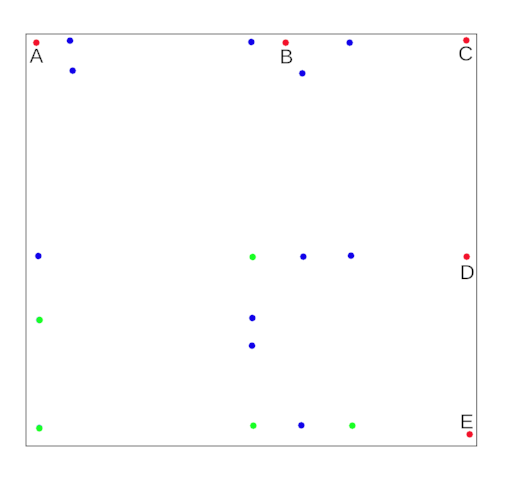
The following schematic shows the positions used by the Talos II motherboard and those supported by the Aurora:

- Green dots are positions used by the Talos II which are also supported by the Aurora.
- Red dots are positions used by the Talos II which are _not_ supported by the Aurora.
- Blue dots are positions which are supported by the Aurora but not used by the Talos II.
Positions A & B
These positions are within the boundaries of the backplate, but close to an edge. I glued some plastic threaded spacers to the backplate with Bondic, which solved the issue for these two positions.
Position C
This position is above a cutout in the backplate. As such it is not possible to install a mounting stud here.
Positions D & E
These positions are above a raised part of the backplate. While studs could be added here, they can not be full height because of the smaller gap. Conversely, there is less room for the board to bend here, especially if the rubber grommets are left in place as support for the board. I opted to leave these mounting positions unused, and just wedge a wad of papers in the gap to support the motherboard when installing DIMMs. I also taped a single sheet of paper between the motherboard and the raised part of the backplate as insulation, just in case.
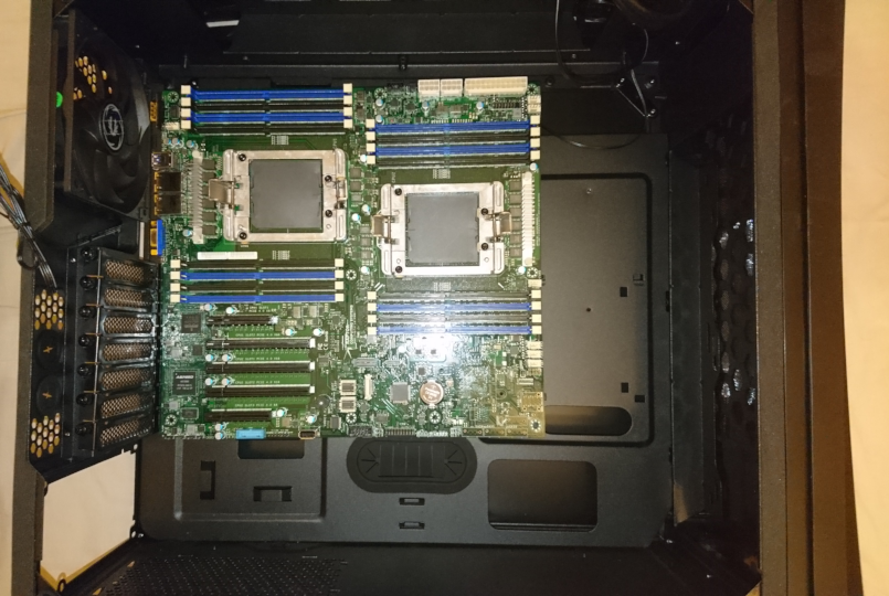
Board position in case
The following picture shows the motherboard positioned in the case
